TowerCalc
Step 1: Titan Tower
| Height | |||||||||||
|---|---|---|---|---|---|---|---|---|---|---|---|
| Model | 16 ft | 24 ft | 32 ft | 40 ft | 48 ft | 56 ft | 64 ft | 72 ft | 80 ft | 88 ft | 96 ft |
| T200 | |||||||||||
| T300 | |||||||||||
| T400 | |||||||||||
| T500 | |||||||||||
| T600 | |||||||||||
| T700 | |||||||||||
| T800 | |||||||||||
Step 2: Wind Conditions
Enter maximum wind condition in the box. If you don't know the precise figure, consult your local weather office or building code.
|
Notes: Tower loading conditions are solely based on wind and antenna loads, and do not allow for icing on either the tower or antenna. However, industry standards allow for an adjustment of wind speed when maximum ice conditions occur. For 1/2” ice, a rule of thumb is to increase the 'test' wind speed by 25% to account for 1/2" of ice. For example, a 75 mph wind speed with 1/2" ice would be similar to 94 mph with no ice. In this example, let's say your tower location experiences maximum wind speeds of 75 mph and maximum radial ice is 1/2". Therefor, you select a wind speed in TowerCalc of 75x1.25 = 94 mph. After inputting all other data and pressing "calculate", the safety factors returned will determine whether this tower configuration survives or fails. If it survives, then you can safely say that the tower will survive 75 mph wind with 1/2" of ice. If the safety factors are below 1.0 then you must say that the tower cannot survive 75 mph winds with 1/2" ice. If you don't
know the wind speed, consult your local weather office. Other sources
may include your local building authority or building codes. The
maximum windspeed is defined as the maxium "3 second gust"
experienced, typically over the past 30 or 40 year period. In Canada,
you may phone Enviroment Canada to speak with a meteorologist for
approximately $3.25 per minute. Their phone number 1-900-565-1111.
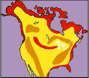
Similar services may exist in the U.S.A. This map of North America
provides only representative wind zones and should not be used as
a substitute for verified data.
|
|
Step 3: Antenna
| Antenna Name | Projected Area (ft2) | Shape | Antenna's Vertical Height (ft) | Antenna Weight (lbs) | Elevation Above Grade | Offset (ft) |
|---|---|---|---|---|---|---|
|
Notes:
Transmission lines: Note
that TowerCalc assumes a transmission line loading of 3 coaxial
lines, 1 inch face mounted on the tower. In order to reduce wind
loading on the tower, we suggest that all coaxial lines should be
tied to the tower leg. Weight - When side-mounting antennas utilizing official Titan Side Mount Kits, an average weight of 30 lbs. per kit should be added to the antenna weight. Titan Side Mount Kits range from 22.2 lbs. for a #2 section, to 34.5 lbs. for a #12 section. Elevation - The “elevation” of an antenna, whether top-mounted in a vertical (upright) position or side-mounted in a vertical (upright) position, is the distance from the ground to the vertical midway point of the antenna.
For example, the elevation of a 12 ft.-high base antenna installed a top a 96-ft. tower is 102 ft. As another example, the elevation of a 10 ft.-high antenna side-mounted at the 80-ft. mark is 85 ft. This Towercalc program requires the antenna height to be inputted and automatically adds 1/2 the height to the elevation behind the scenes. If the antenna is horizontally oriented, the user must input "zero" in the field. Offset - The “offset” is the distance from the center of the tower to the point of attachment of a side-mount antenna. The offset distance is measured in feet and is entered in decimal points: for example “5.5”. It's very important to include offset distance because the greater that distance, the more force is exerted on the tower.
Titan Side Mount Kits have a built-in offset ranging from 0.25 ft. for a #2 section to 2 ft. for a #12 section. That's because you must include the distance from the center of the tower (inside) to the point on the side mount pipe where the antenna will be attached. These are the automatic offset distances for each section:
If you will
offset the antenna even further, then you must add that extra distance
to the built-in offsets stated above for each section.
(Please note that Trylon TSF does not accept responsibility for user assumptions.) |

Results